LD14雷达与STM32F103RCT6
LD14激光雷达介绍
基本介绍
乐动激光雷达LD14共有四个接口,使用1.25mm 连接器与外部系统连接。具体定义与参数见《开发手册》中图。
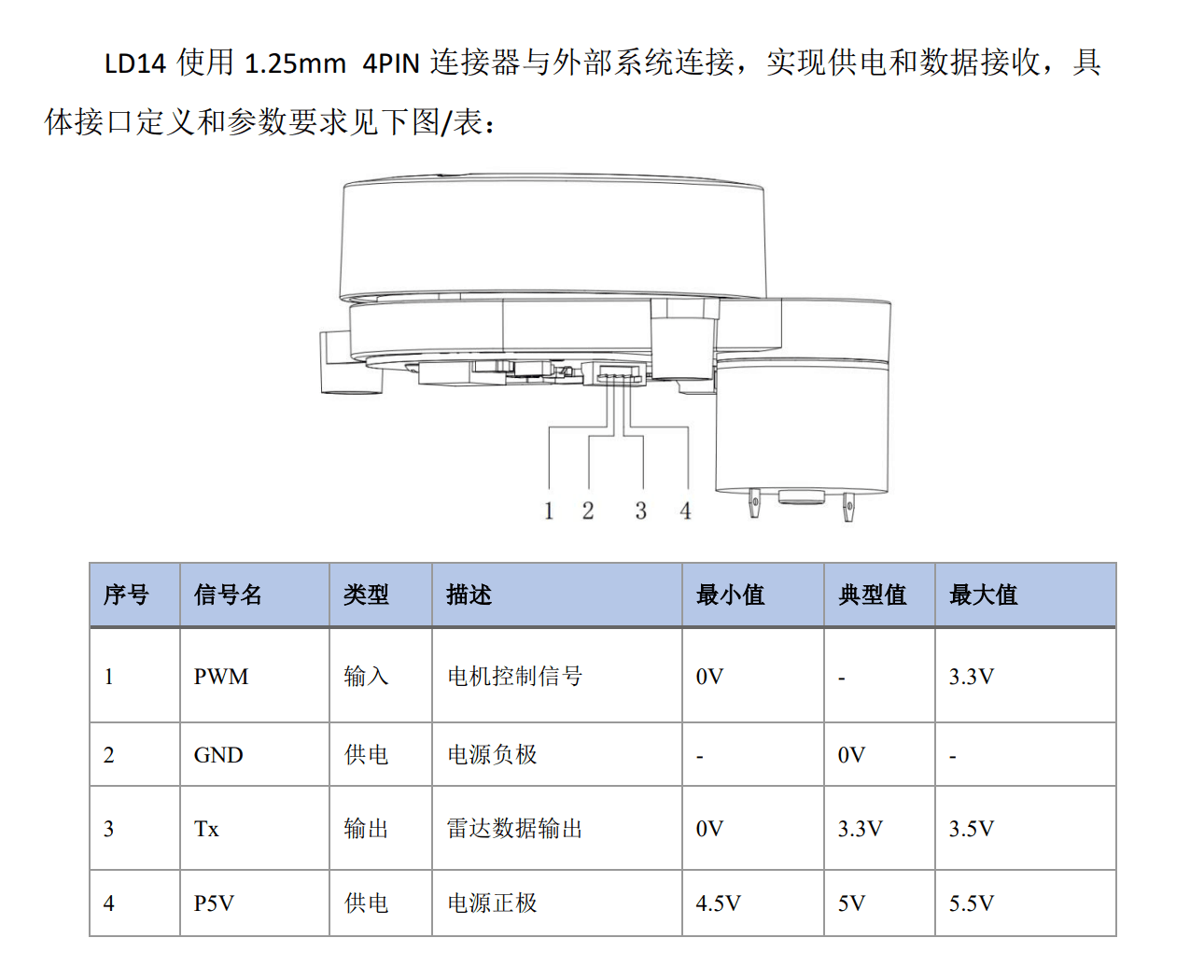
在不要求PWM控制雷达转速的情况下可以将PWM接口悬空,默认以6Hz转速旋转。
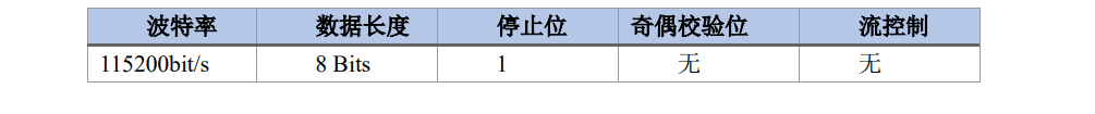
数据通讯采用标准异步串口单向发送,参数如图。
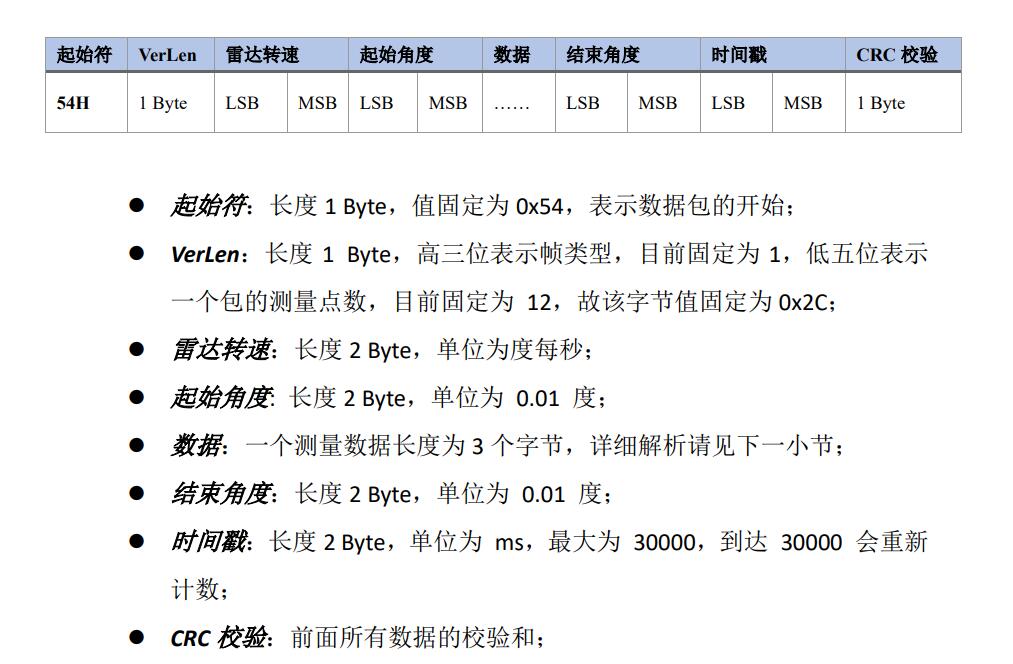
接线正确稳定工作后,雷达将会自动开始通过串口通信发送数据包。
示例
使用示例讲解数据包,假设其中一组数据包内容如下。
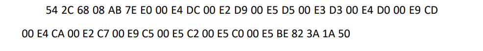
前两个数据分别是起始符与VerLen,为固定值,后两个分别为雷达转速十六进制表达的后八位与前八位。自此开始,是各点测量数据。在一个数据包中,将会有12个点数据,每个点数据又由距离值(前两个数据)与置信度(后一个数据)组成,前两个数据分别是距离值十六进制表示的后八位与前八位。在默认转速下,一个数据包内起始角到终止角约12度,每一个角数据约1度。原始数据由于三角测距原理,需要后续修正。
注意
LD14使用左手坐标系,旋转中心为坐标原点,旋转角度沿顺时针增大。
STM32F103RCT6使用
准备
将STM32F103RCT6的USART3与USART1使能,RCC配置如下
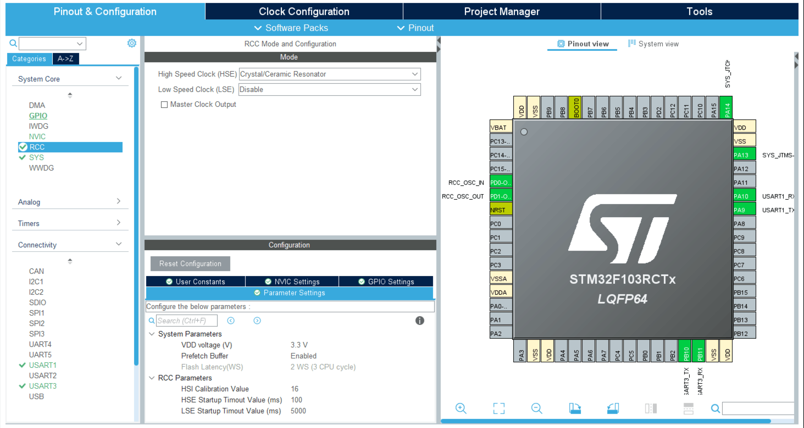
Clock Configuration HCLK 72 max 配置。
编程
借助开发手册与示例,根据三角测速原理,在main文件或usart3文件中进行数据修正与处理。
1
2
3
4
5
6
7
8
9
10
11
12
13
14
15
16
17
18
19
20
21
22
23
24
25
26
27
28
29
30
31
32
33
34
35
36
37
38
39
40
41
42
43
44
45
46
47
48
49
50
51
52
53
54
55
56
57
58
59
60
61
62
63
64
65
66
67
68
69
70
71
72
73
74
75
76
77
78
79
80
81
82
83
84
85
86
87
88
89
90
91
92
93
94
95
96
97
98
99
100
101
102
103
104
105
106
107
108
109
110
111
112
113
114
115
116
117
118
119
120
121
122
123
124
125
126
127
128
129
130
131
132
133
134
135
136
137
138
139
140
141
142
143
144
145
146
147
148
149
150
151
152
153
154
155
156
157
158
159
160
161
162
163
164
165
166
167
168
169
170
| void USART3_IRQHandler(void)
{
static u8 state = 0;
static u8 crc = 0;
static u8 cnt = 0;
u8 temp_data;
if(USART_GetITStatus(USART3, USART_IT_RXNE) != RESET)
{
temp_data=USART_ReceiveData(USART3);
USART_ClearITPendingBit(USART3,USART_IT_RXNE);
if (state > 5)
{
if(state < 42)
{
if(state%3 == 0)
{
Pack_Data.point[cnt].distance = (u16)temp_data;
state++;
crc = CrcTable[(crc^temp_data) & 0xff];
}
else if(state%3 == 1)
{
Pack_Data.point[cnt].distance = ((u16)temp_data<<8)+Pack_Data.point[cnt].distance;
state++;
crc = CrcTable[(crc^temp_data) & 0xff];
}
else
{
Pack_Data.point[cnt].confidence = temp_data;
cnt++;
state++;
crc = CrcTable[(crc^temp_data) & 0xff];
}
}
else
{
switch(state)
{
case 42:
Pack_Data.end_angle = (u16)temp_data;
state++;
crc = CrcTable[(crc^temp_data) & 0xff];
break;
case 43:
Pack_Data.end_angle = ((u16)temp_data<<8)+Pack_Data.end_angle;
state++;
crc = CrcTable[(crc^temp_data) & 0xff];
break;
case 44:
Pack_Data.timestamp = (u16)temp_data;
state++;
crc = CrcTable[(crc^temp_data) & 0xff];
break;
case 45:
Pack_Data.timestamp = ((u16)temp_data<<8)+Pack_Data.timestamp;
state++;
crc = CrcTable[(crc^temp_data) & 0xff];
break;
case 46:
Pack_Data.crc8 = temp_data;
if(Pack_Data.crc8 == crc)
{
receive_cnt++;
data_process();
}
else
memset(&Pack_Data,0,sizeof(Pack_Data));
crc = 0;
state = 0;
cnt = 0;
default: break;
}
}
}
else
{
switch(state)
{
case 0:
if(temp_data == HEADER)
{
Pack_Data.header = temp_data;
state++;
crc = CrcTable[(crc^temp_data) & 0xff];
} else state = 0,crc = 0;
break;
case 1:
if(temp_data == LENGTH)
{
Pack_Data.ver_len = temp_data;
state++;
crc = CrcTable[(crc^temp_data) & 0xff];
} else state = 0,crc = 0;
break;
case 2:
Pack_Data.speed = (u16)temp_data;
state++;
crc = CrcTable[(crc^temp_data) & 0xff];
break;
case 3:
Pack_Data.speed = ((u16)temp_data<<8)+Pack_Data.speed;
state++;
crc = CrcTable[(crc^temp_data) & 0xff];
break;
case 4:
Pack_Data.start_angle = (u16)temp_data;
state++;
crc = CrcTable[(crc^temp_data) & 0xff];
break;
case 5:
Pack_Data.start_angle = ((u16)temp_data<<8)+Pack_Data.start_angle;
state++;
crc = CrcTable[(crc^temp_data) & 0xff];
break;
default: break;
}
}
}
}
void data_process(void)
{
static uint8_t data_cnt_avoid = 0;
uint8_t i = 0;
float start_angle = Pack_Data.start_angle/100.0;
float end_angel = Pack_Data.end_angle/100.0;
if(start_angle>=360)
start_angle -= 360;
if(end_angel>=360)
end_angel -= 360;
float average_angel;
if((start_angle -= 180)<0)
start_angle += 360;
if((end_angel -= 180)<0)
end_angel += 360;
if(start_angle>end_angel) end_angel +=360;
average_angel = (end_angel - start_angle)/11;
if(1)
{
for(i=0;i<12;i++)
{
AvoidData[data_cnt_avoid].angle = start_angle + i*average_angel;
if(AvoidData[data_cnt_avoid].angle>=360)
AvoidData[data_cnt_avoid].angle -= 360;
AvoidData[data_cnt_avoid].distance = Pack_Data.point[i].distance;
if(++data_cnt_avoid == 100)
data_cnt_avoid = 0;
}
}
}
|
定义如下结构体
1
2
3
4
5
6
7
8
9
10
11
12
13
14
15
16
17
18
19
20
21
22
23
24
| typedef struct __attribute__((packed)) Point_Data
{
u16 distance;
u8 confidence;
}LidarPointStructDef;
typedef struct __attribute__((packed)) Pack_Data
{
uint8_t header;
uint8_t ver_len;
uint16_t speed;
uint16_t start_angle;
LidarPointStructDef point[POINT_PER_PACK];
uint16_t end_angle;
uint16_t timestamp;
uint8_t crc8;
}LiDARFrameTypeDef;
typedef struct __attribute__((packed)) PointDataProcess_
{
uint16_t distance;
float angle;
}PointDataProcessDef;
|
在USART1加入处理代码使其满足printf()函数使用
1
2
3
4
5
6
7
8
9
10
11
12
13
14
15
16
17
18
19
20
21
22
23
| #if 1
#pragma import(__use_no_semihosting)
struct __FILE
{
int handle;
};
FILE __stdout;
void _sys_exit(int x)
{
x = x;
}
int fputc(int ch, FILE *f)
{
while((USART1->SR&0X40)==0);
USART1->DR = (u8) ch;
return ch;
}
#endif
|
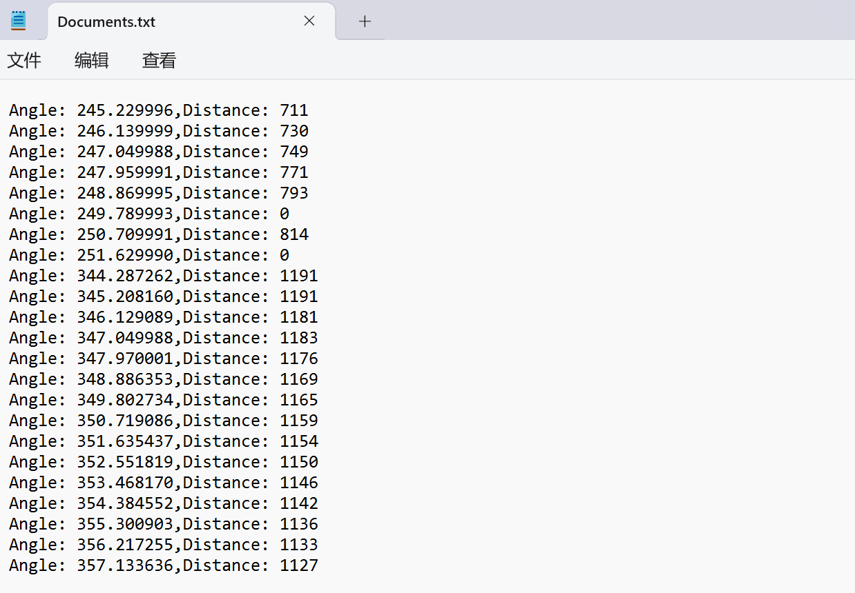
初始化、开启各中断后在while中输出Avoid_Data数组即可获得数据。
通过串口调试助手保存后如图
Matlab处理点云数据
编程
在Matlab中读取保存好的点云数据
1
| data1 = fileread('Documents.txt');
|
由于我控制输出流格式,使用正则表达式提取相应数据
1
2
| angle_pattern = 'Angle: ([\d\.]+)';
distance_pattern = 'Distance: (\d+)';
|
转化为数值,注意角度转换为弧度制
1
2
3
4
| angle_matches5 = regexp(data5, angle_pattern, 'tokens');
distance_matches5 = regexp(data5, distance_pattern, 'tokens');
angles5 = cellfun(@(x) str2double(x{1}), angle_matches5);
distances5 = cellfun(@(x) str2double(x{1}), distance_matches5);
|
转化为笛卡尔坐标系,便于多点采样后解决坐标变换问题。
1
2
3
4
5
| x1 = distances1 .* cos(angles1_rad);
y1 = distances1 .* sin(angles1_rad);
x2 = distances2 .* cos(angles2_rad)+900;
y2 = distances2 .* sin(angles2_rad)+80;
|
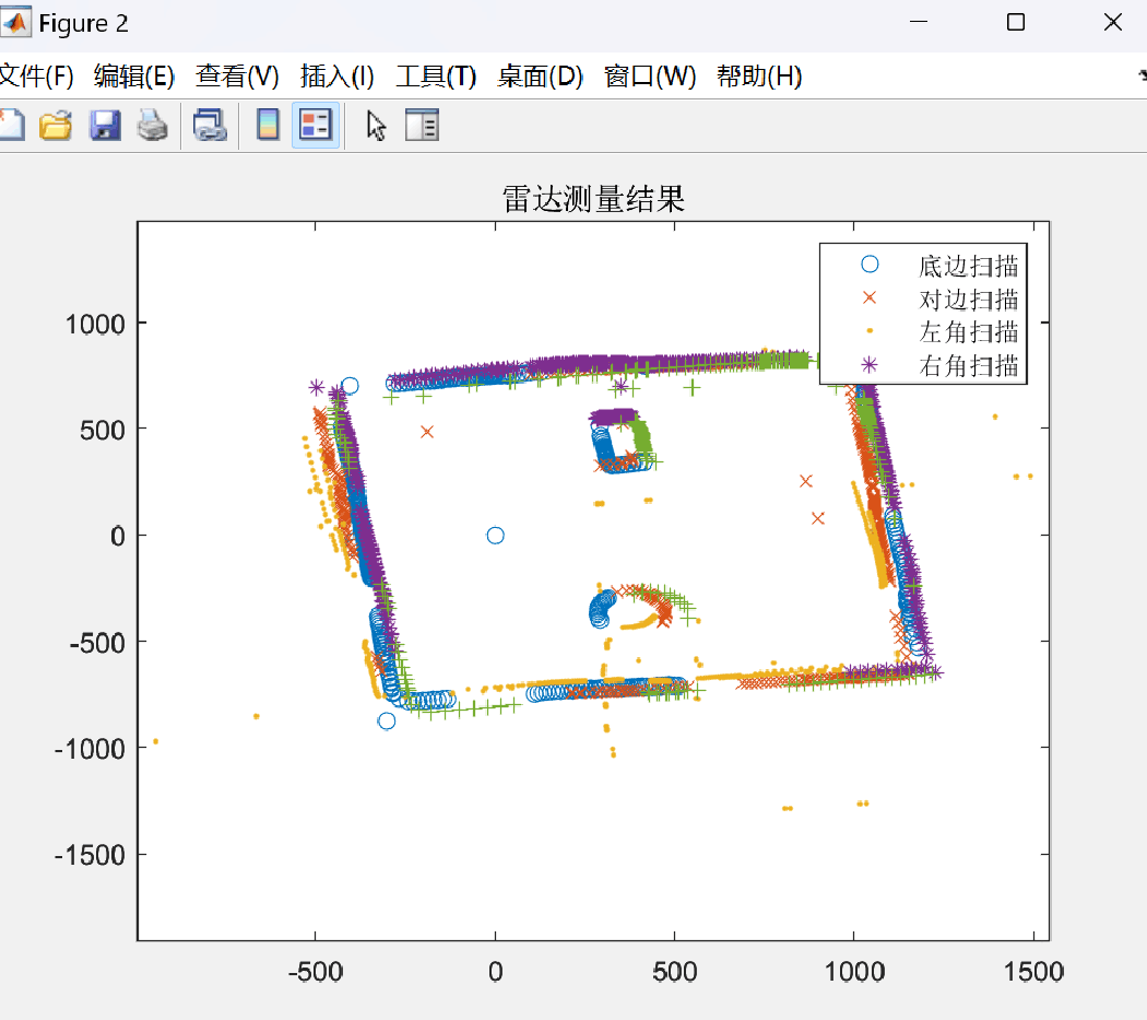
最后 plot() 绘制图像即可
效果如下
反思
在点云数据保存处理过程中,由于信息传输过快,串口打印有几率出现乱码,Matlab数据处理时有几率出现数据大小运算不相容的状况,可自己编写程序自动化修改数据。
参考文献
《LD14用户开发手册》
《LD14数据手册》
LD14雷达STM32F103C8T6获取LD14激光雷达数据